|
|
Electrical Transducers
|
|
|

Model T-INTP
|
T-INTP DC Integrator Transducer
The T-INTP integrator converts a dc signal into pulses.
The frequency of the pulses is directly proportional to the amplitude of the input.
The number of pulses produced is a mathmatical integral of the input signal and may be used to derive kW-hour, amp-hour and similar rate quantities.
The output pulses are available from either relay contacts, open collector or opto-coupler.
|
| Basic Specifications: |
| Input | Current Imin-Inom | : 0-10mA, 0-20mA or 4-20mA dc |
| (others on request) | Voltage 0-Vnom | : 0-50mV, 0-5V or 0-10V dc |
| Output | Pulse rate proportional to input |
| | : Standard relay |
| | : Open collector |
| | : Opto-coupler |
| Accuracy | | : Class 0.5 IEC 60688 |
| Range | : 0-120% |
| Auxiliary Supply | | : 24V, 110V, 230/240V, 400/415V ac ±20%, 2VA |
| | : 12V, 24V, 48V, 110V dc ±20%, 2W |
| Isolation | Galvanic isolation between input, output and auxiliary supply |
| Test voltage | : 4kV 50Hz ac for 1 minute |
| Temperature | Operating | : -10°C to +20°C to +50°C |
| EMC Compliance | : AS/NZS 61000.6.3:2012 |
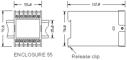
| Dimensions |
 |
|
|
